As part of my final year at University I completed a dissertation titled “Techniques for the utilisation of heterogeneous multi-GPU configurations in realtime rendering”. This paper provides an early proof of concept for real time heterogeneous multi-GPU rendering. However, the research had to be completed in a fairly narrow time-frame, around 6 months in addition to a large amount other work. This meant that the final implementation wasn’t polished and some areas of investigation (such as shadow mask compression) had to be left out.
Currently, engine development time is being spent improving the renderer and DirectX 12 implementation. Once this work is completed I plan to revisit the techniques presented in this paper in much greater detail (and some new techniques as well).
An RHI is the abstraction layer between a graphics API and the renderer. It allows the renderer to be completely API independent. Also, the RHI abstract API concepts to provide a simpler interface for the renderer.
RHI overview
Adept engine uses a command list oriented RHI, meaning that all standard commands like draw, resource binding and state setting are called on a command list object. The main reason for this design was a close abstraction for DirectX 12’s command lists and Vulkan’s command buffers. Additionally, they simplify use of the different command queues (compute, copy etc.) and allow for easy and efficient threading.
The Device Object
To support multi-GPU a single static device object cannot be used. Every RHI object needs a device reference. The device context class is implemented by each graphics API and controls all the data on that GPU. This allows the rendering code to handle multi-GPU directly making more multi-GPU techniques possible. This does have the disadvantage of the rendering code needing to handle each GPU case explicitly. However, this is largely mitigated by the render graph system(link).
Hardware interfacing
Normally a single ID3D12Device object is created for each GPU in a system and this maps directly to a device context object in the engine.
Linked GPUs are reported as a single ID3D12Device with the node count (and mask) representing the GPUs. The engine creates a separate device context for each node (See diagram below). The node index/mask is used to control the correct GPU in the set. This allows both unlinked and linked GPU sets to appear identical to the rendering code allowing better code reuse. Currently Vulkan only supports linked GPU sets.
It is possible to have a scenario with 3 GPUs in a system with 2 linked and 1 unlinked (see below). This is handled without issue as the Inter-GPU copy commands are aware of this and will use the fastest transfer method between the GPUs automatically.
Mapping of GPUs to Device Contexts (SLI is Nvidia’s Linked adaptor technology)
Synchronisation
Each device has several command queues associated with it, these require synchronization between themselves, the CPU and other GPUs. This is managed though the Insert wait command which signals a fence on one queue and then wait for it on another. Any queue on any device can be singled or waited for. The RHI implementation handles the API specific functions. Additionally, a GPU Sync Point object can be created, which act like a win32 event, useful when more complex synchronisation is needed. Though this system simple synchronisation is easy to implement, normally in a single line.
Staging resources
To copy between unlinked GPUs a resource must first be copied to host (CPU) memory, this CPU memory is represented as an Inter-GPU staging resource object in the engine. It is a type of storage node in the render graph system and can be used for multiple different transfers (although not at the same time). When created, space is allocated for several framebuffers (or buffers) that need to be transferred concurrently. The staging resource tracks any resources that are copied to and from it to avoid data overwrite.
The process starts with an asynchronous copy from the source GPU to the staging resource. Next the destination GPU copies It from the staging resource as soon as possible. Ideally the whole transfer is done asynchronously on the copy queue (DMA engines) so the data is ready on the destination GPU before it is needed avoiding an execution stall, which could reduce GPU performance.
Linked GPUs can transfer data directly between each GPU’s video memory and so don’t use this object. While this does increase renderer complexity, helper functions are provided that handle both cases seamlessly.
Threading
Command Lists are free threaded allowing draw calls to be recorded in parallel. Currently, submission of lists to the GPU is done by the main render thread when they are finished. This allows lists to be grouped into a single API call which provides performance advantages from the driver. For a system with many GPUs (3+), an additional submission thread could improve performance.
Adept engine uses a Command List Group object to make threading of the draw passes simpler. This object holds a commands list for each thread to use. It will handle setting the correct render passes on all the lists, allowing a single render pass to span all the command lists rather than just one. It will also handle submitting all the lists in the same call, a requirement of spanning the render pass.
Supporting non-explicit APIs
Adept engine only supports DirectX 12 and Vulkan which are both explicit APIs and there are no plans to support DirectX 11. However, DirectX 11 could be implemented within the command list RHI either using direct command submission or using deferred contexts (which provides a method of allowing limited threading of commands). It would be up to the renderer to handle the lack of threading in the DirectX 11 API (when using direct submission).
A render graph (or frame graph) is a way of defining the rendering pipeline using self-contained nodes in an acyclic directed graph. Each node has a set of input and outputs, which link to other nodes or resources. When executed, the graph is traversed executing each node in turn.
One major advantage is the ability to traverse the graph before run time to collect useful data such as resource state transitions, temporary resource use etc. Also, the modular nature of the nodes allows for easy reuse. This architecture allows an engine to support many different renderer configurations without large amounts of code duplication or an unmanageable number of conditionals statements.
In the simple example below the ellipse represents the frame buffer resource needed by the Debug UI node which is then passed to the output to screen node to be displayed on screen.
Simple Render graph example
Adept engine’s implementation
Adept Engine uses render graph instances to handle the many renderer cases present in modern rendering. Each instance is made up of a graph and several patches which are applied at build time. This allows a small set of render graphs to be defined and patches used to add support for extra features. For example, only a patch to is needed to add support for ray traced reflections rather than create an entire new graph. This same patch could be applied to a forward renderer or a VR render graph without any changes to the base graph definition. This approach allows the engine to support raytracing, VR and multi-GPU rendering with ease and little to no code duplication.
Flow control
In both VR and Multi-GPU rendering, the same rendering passes are repeated multiple times (possibly with slightly different data). Creating a graph that has two rendering passes would work for VR but would cause lots of duplication for Multi-GPU as a new graph would be needed for each GPU in the system. The solution to these issues is the loop node, for VR this loops round twice changing the eye index used. For Multi-GPU ,the nodes are just looped on each GPU (having already been initialised on the respective GPU). All the logic for splitting the frame up is handled by each node based on the device index.
Advantages to normal rendering:
Scheduling
Adept engine uses a fixed graph, where each node is placed manually in the base graph however a graph could use automatic scheduling with each node just listing its dependencies. This would allow for automatic compute work scheduling etc. Unreal Engine 4 (Epic Games) is implementing this approach with their new Render Dependency Graph (more HERE).
Barriers
As the engine has complete knowledge of all the rendering commands ahead of execution, optimal resource barriers can be used. Each node has a start and end state for all its resources. This helps to simplify placement of resource barriers needed in explicit level APIs (Dx12, Vulkan etc.).
The compute pipeline requires resources to be in a compatible state before being used on compute. Commonly the resource is in a state for graphics which means a graphics pipeline must transition it out of that state. Using an informed barrier system, this is handled with ease as the previous graphics node is aware of that the next work is compute so transitions the resource at the end of its work.
This system also supports split barriers, these define a start and end for a state transition and allow the driver to better optimise the transition (more HERE).
Multi-GPU rendering:
One of the key advantages to the render graph architecture is easy support for multi-GPU rendering. With the addition of inter-GPU transfer nodes, Multi-GPU support is as simple as adding a new graph. Using loop nodes supporting N number of GPUs is relatively easy.
Disadvantages:
There is a reasonable amount of work needed to create the core node system and render graphs. Porting an existing engine to this architecture could be a very large task. At runtime, there is a small amount of overhead as the system is more complex than a set of simple function calls that a traditional renderer would have.
What is it? View instancing allows a shader to be run multiple times in a single draw call to draw different instances. The SV_ViewID semantic is provided to the shader which defines the index of the view instance. The advantage to using this API is the support of hardware acceleration and simplicity of multi view shading.
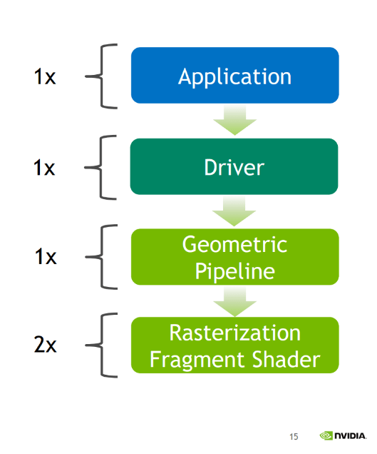
Hardware Support: Nvidia’s Turing architecture (RTX 20 Series) implements this API as “Multi-View rendering” and supports 4 arbitrary views in hardware and up to 32 software views (see below). Pre-Turing GPUs have up to 32 software views and no hardware views. Interestingly Pascal (GTX 10 Series) does support single pass stereo which is hardware acceleration for 2 views ports however view instancing cannot make use of this, most likely due to a lack of flexibility in the hardware.
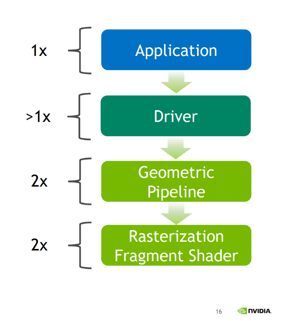
Pipeline for a software View
Pipeline for a hardware View
Software Views: A software view sounds largely redundant however they reduce CPU overhead by allowing the application to record commands once and the driver can follow a fast path to reduce CPU overhead further. There is no major advantage on the GPU, the driver just loops the draw calls changing the viewID. (See above)
Setup: To use view instancing the GPU must support D3D12_VIEW_INSTANCING_TIER_1 or greater. Support can be queried though the D3D12_FEATURE_DATA_D3D12_OPTIONS3 data struct. The API currently limits the number of view instances in a draw command to 4.
Pipeline State Object (PSO): This API requires the use of the PSO extensions API. It is recommended use the “d3dx12.h” helper header provided here.
The D3D12_VIEW_INSTANCING_DESC struct provides the ability to define a render target or view port index for each view. This index is added to the SV_RenderTargetArrayIndex set in a shader. Both methods are fully supported.
Shaders: To access the SV_ViewID semantic shaders must be built with Shader model 6.1 or above. This requires the use of the new DIXL complier available here.
View instancing for point light shadow mapping: In this example, view instancing is used to capture cube shadow maps for a point light. Due to the 4-view limit, two render passes are used with 3 view instances per pass. There are 4 point lights in the scene. The scene contains a number of varied meshes,the object count is the number of shadowing meshes.
Results: The following results were captured on a GTX 1080 (pascal).
Object count
Metric
CPU
Geometry shader
View instancing
36 objects
GPU
2.50ms
4.01ms
2.60ms
36 objects
CPU time
0.63ms
0.28ms
0.36ms
1036 objects
GPU
13.70ms
16.30ms
16.01ms
1036 objects
CPU time
12.20ms
4.40ms
6.50ms
In the small scene the geometry shader is slower on the GPU but has the best CPU time. In the large scene it is much closer to the GPU time of view instancing with a slightly better CPU time.
The reduced CPU overhead of view instancing is very apparent in the large scene with an improvement of almost half (5.7ms faster) over CPU rendering.
Instance masking: The API exposes a function to mask off views from being rendered to. This must be enabled in the PSO first. Then the “SetViewInstanceMask” (DOCS) function can be used to set the mask at draw time.
This blog contains an insight into the development of the Adept engine and other things relating to game development. The engine is open source so feel free to use any source code from it: github.com/Andrewcjp/Adept-Engine
Most of the articles on this blog are not intended to be complete tutorials rather concepts/ideas with code examples.